
Key takeaway:
- Draft angles, parting line placement, and rib-to-wall ratios are the most frequent sources of design friction in impression die forging projects.
- Early collaboration between design engineers and forging suppliers reduces tooling rework and shortens lead times.
- Material selection and finish allowances must be locked in before die design begins to avoid costly mid-project changes.
Engineers designing parts for impression die forging most often run into trouble with draft angles, parting line geometry, and rib or wall proportions that ignore how metal actually flows inside a closed die. These issues surface late in the process, usually after tooling has already been cut, which drives up cost and delays production schedules.
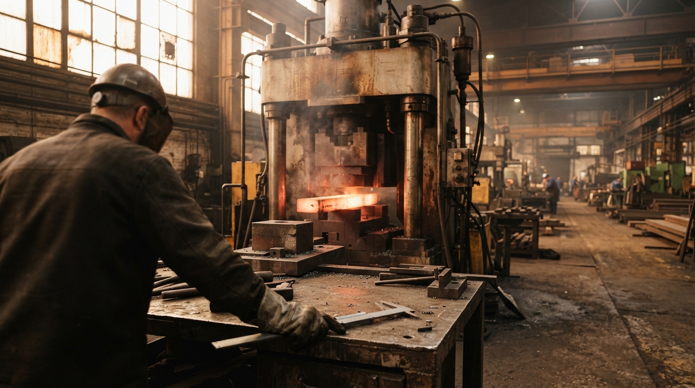
Getting ahead of these problems starts with understanding how the process itself constrains geometry. Impression Die Forging forces heated metal into a die cavity under extreme pressure, and every dimension on a part drawing has to account for die wear, shrinkage, and flash removal. A design that looks clean on a CAD screen can still fail in production if it does not respect these physical realities.
Geometry Problems That Trip Up New Designs
Most impression die forging setbacks trace back to a handful of recurring geometry mistakes. Design teams who catch these early avoid the expensive cycle of re-cutting dies after a first trial run.
- Insufficient draft angles. Steel forgings typically need draft in the 5 to 7 degree range, and skipping this makes parts stick in the die and tear on ejection.
- Poorly placed parting lines. A parting line set near an edge instead of through the part’s center creates uneven flash and inconsistent fill.
- Sharp internal corners. Tight fillets restrict metal flow and concentrate stress, shortening fatigue life in the finished part.
- Unbalanced rib and wall thickness. Ribs that are too tall and narrow relative to the web starve the die cavity of material during the forging stroke.
The Forging Industry Association’s product design guide outlines these principles in detail, including guidance that ribs and bosses should stay low and wide with generous fillets to keep metal flow balanced across the die cavity. Following that framework at the concept stage prevents most of the rework that shows up during first-article inspection.
Material and Tolerance Tradeoffs
Choosing the right alloy and setting realistic tolerances go hand in hand, and treating them as separate decisions late in a project usually backfires. Carbon steel, alloy steel, and stainless grades each behave differently under compressive load, which changes how tight a tolerance a die can realistically hold.
|
Design Factor |
Common Mistake |
Practical Fix |
|
Draft angle |
Too shallow, causing part sticking |
Apply 5-7 degree draft on steel per FIA guidelines |
|
Parting line |
Placed off-center or near an edge |
Route through the part’s geometric center |
|
Wall/rib ratio |
Ribs too tall and narrow |
Widen ribs, thicken web for even flow |
|
Finish allowance |
Underestimated machining stock |
Add allowance based on part size and alloy |
Tolerances also depend on which portion of the part is being measured. Dimensions fully contained within one die half can hold tighter tolerances than dimensions that cross the parting plane, since those are affected by die closure and flash thickness. Designers who build this distinction into their drawings from the start avoid disputes over acceptable variation later in the qualification process.
Coordinating Design With Downstream Operations
A part drawing that only reflects the forged shape, without considering what happens after the press, tends to create friction with machining and finishing teams. Heat treatment, secondary machining, and inspection all depend on decisions made at the design stage.
- Machining allowances need to account for the worst-case buildup of draft and dimensional tolerance across the part.
- Datum points for downstream machining should be established early so the forged part and the finished part share a consistent reference plane.
- Material certification requirements should be confirmed before die design locks in, since some alloys demand additional testing steps that affect scheduling.
Forging suppliers that manage heat treatment, machining coordination, and material certification under one roof can flag these conflicts before they become production problems rather than after a batch fails inspection.
Frequently Asked Questions
What is the biggest design mistake in impression die forging?
Inadequate draft angle is the most common issue, since it causes parts to stick in the die and can damage both the forging and the tooling during ejection.
Why does parting line placement matter so much?
The parting line determines how evenly the die halves fill with metal. Placing it off-center creates uneven flash and can leave sections of the part underfilled.
Can tight tolerances always be forged as designed?
Not always. Tolerances differ depending on whether a dimension sits within one die half or crosses the parting plane, so tight callouts across the parting line often require negotiation with the forging supplier.
How early should a forging supplier be involved in design?
Ideally before the die is cut. Early input on draft, fillets, and rib proportions prevents the rework that comes from correcting a design after a first trial forging.
Working through these design considerations before finalizing a drawing saves both time and tooling costs once a part moves into production. Manufacturers evaluating a forging partner for a new component can review capabilities and reach out through Cornell Forge Co, a Chicago-based forging company with decades of experience producing complex forged parts for industrial applications.
For more information on Impression Die Forging, Contact Cornell Forge Co at https://www.cornellforge.com/.